CNC310 Breakout Board
If you prefer to use separate wires to hook up your CNC310, this breakout board will help you. Simply stack the CNC310 on top of this board and start wiring your controller.
Purchase

Contents
Each breakout board kit contains the following:
- 1x Breakout board CNC310
- 1x Connection cable CNC310
- 8x 12mm spacers
- 16x M3 bolt 6mm
Overview
Installation
The kit contains all the mounting material to mount a CNC310 controller and the breakout board.
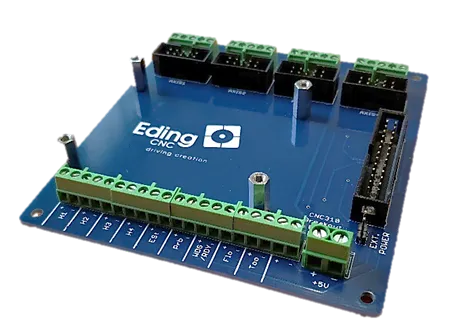
1 Mounting PCB spacers on the breakout board
2 Attaching the cable to the CNC310
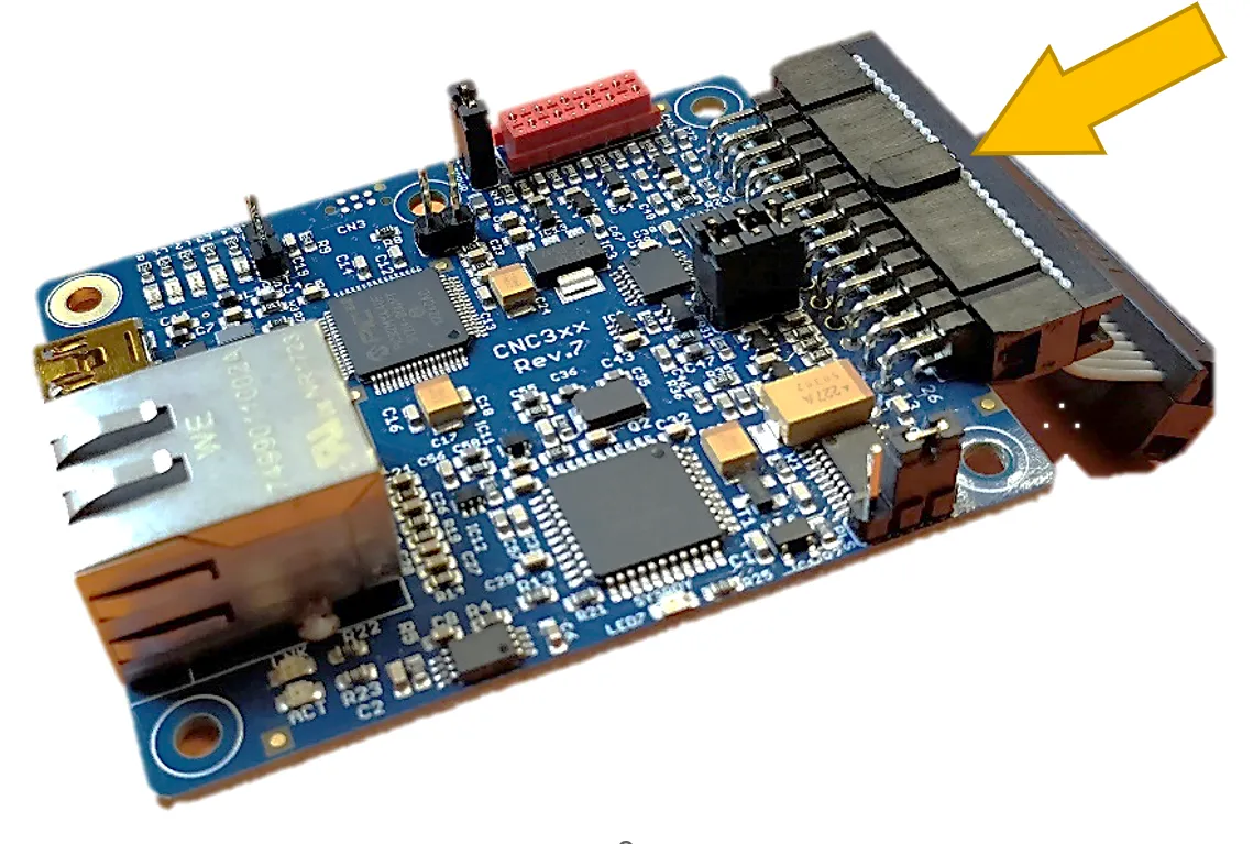
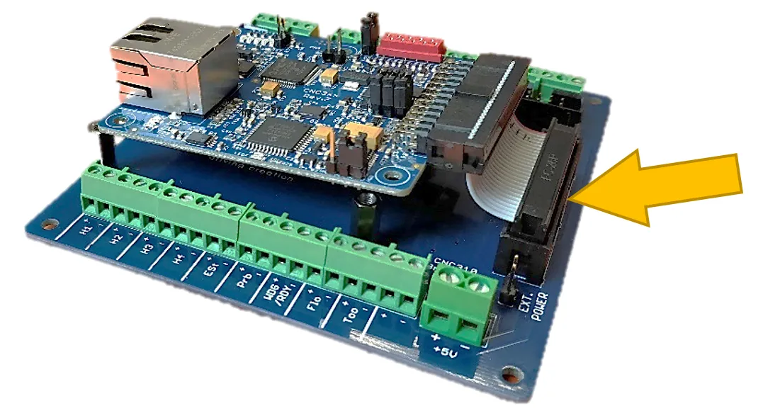
Next, the cable needs to be mounted, make sure the orientation is correct.
3 Connecting the CNC310 to the breakout board
Connect the CNC310 by inserting the cable into the box header on the breakout board.
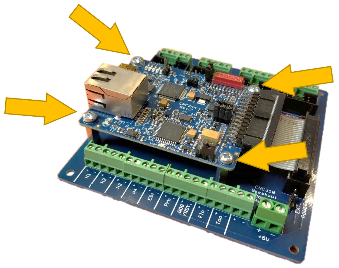
4 Mounting the CNC310
Use 4 M3 screws to mount the CNC310 on the spacers.
Setup
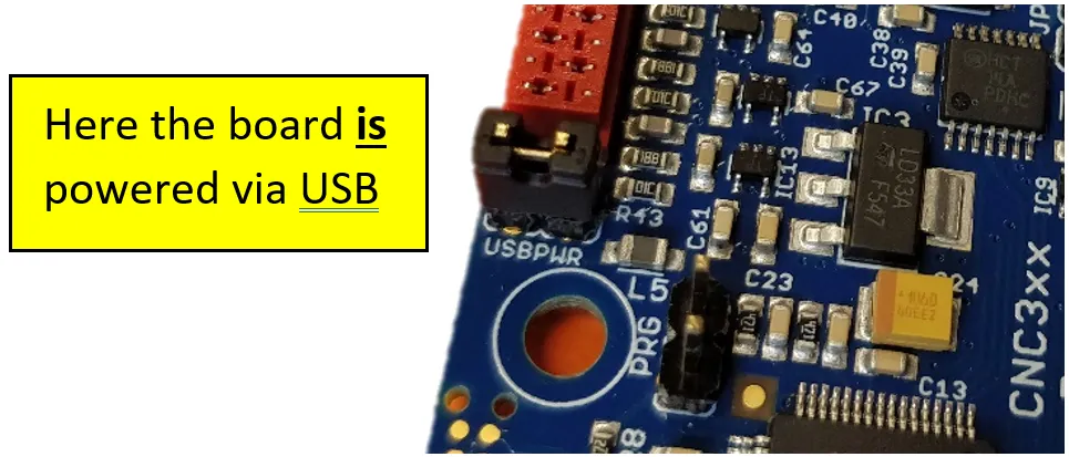
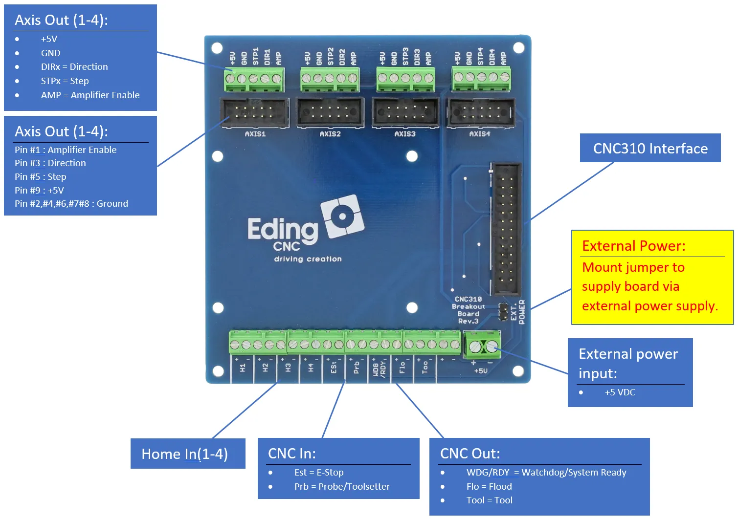
This board can either be externally powered with 5V. By default, the 'EXT. POWER' jumper is not set. If you want to power it externally with 5V the jumper must be set to 5V.
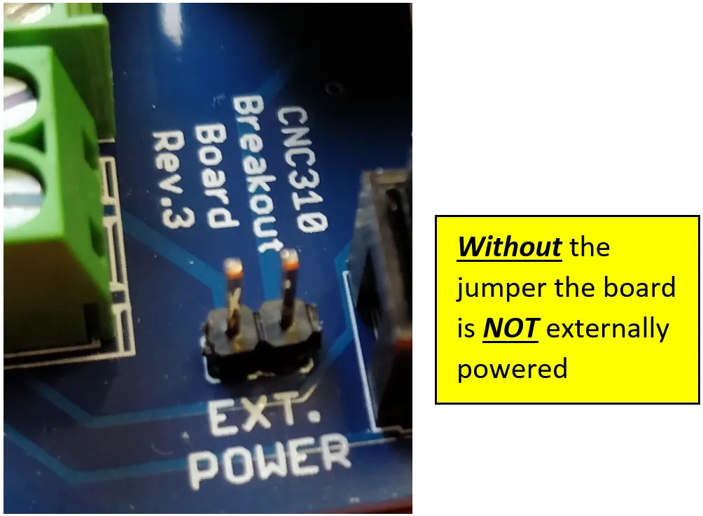
If external power is applied, the jumper USBPWR on the CNC310 must be removed to avoid the PC's USB port being powered externally.