2. Connecting an E-stop switch
Introduction
An Emergency Stop (E-Stop) switch is a critical safety feature used in CNC machines, to ensure the safety of the operator and equipment in case of an emergency.
The main purpose of the E-stop switch is to stop the machine immediately when an unexpected hazard occurs. This might be mechanical failures, broken tools, unintended movements, and or threats to the operator.
Install one or more E-stop switches in places where they are visible and easily reachable from all sides of the machine.
To comply with local safety regulations, please check to see if the use of a safety relay is required. Failure to comply with these regulations may result in liability issues.
The CNC720's E-stop circuitry is only designed to notify the operator of an emergency condition. The outputs that are being turned off from the CNC720 cannot be the only safety measure and their power should be cut off directly.
Installation will be different depending on whether a safety relay is used.
The CNC720 has integrated circuits that disable all outputs if E-STOP is active. This is indicated by a RED indicator on the CNC720 board next to the E-STOP input.
Connect E-STOP switch
Directly to CNC720
The CNC720 has a dedicated input for E-stop signal
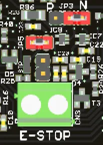
Behind the E-STOP connector is a jumper JP4 that can bypass it. Make sure there is no jumper in place. For more info about the jumper, refer Technical manual
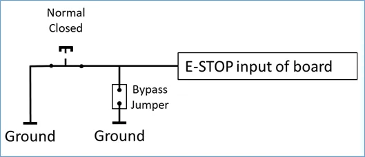
The E-STOP inputs must be connected to a ‘normally closed’ (NC) switch. As a result, if the E-STOP cable has a broken wire, this will automatically trigger an E-STOP condition.
Directly to CNC720 Breakout Board
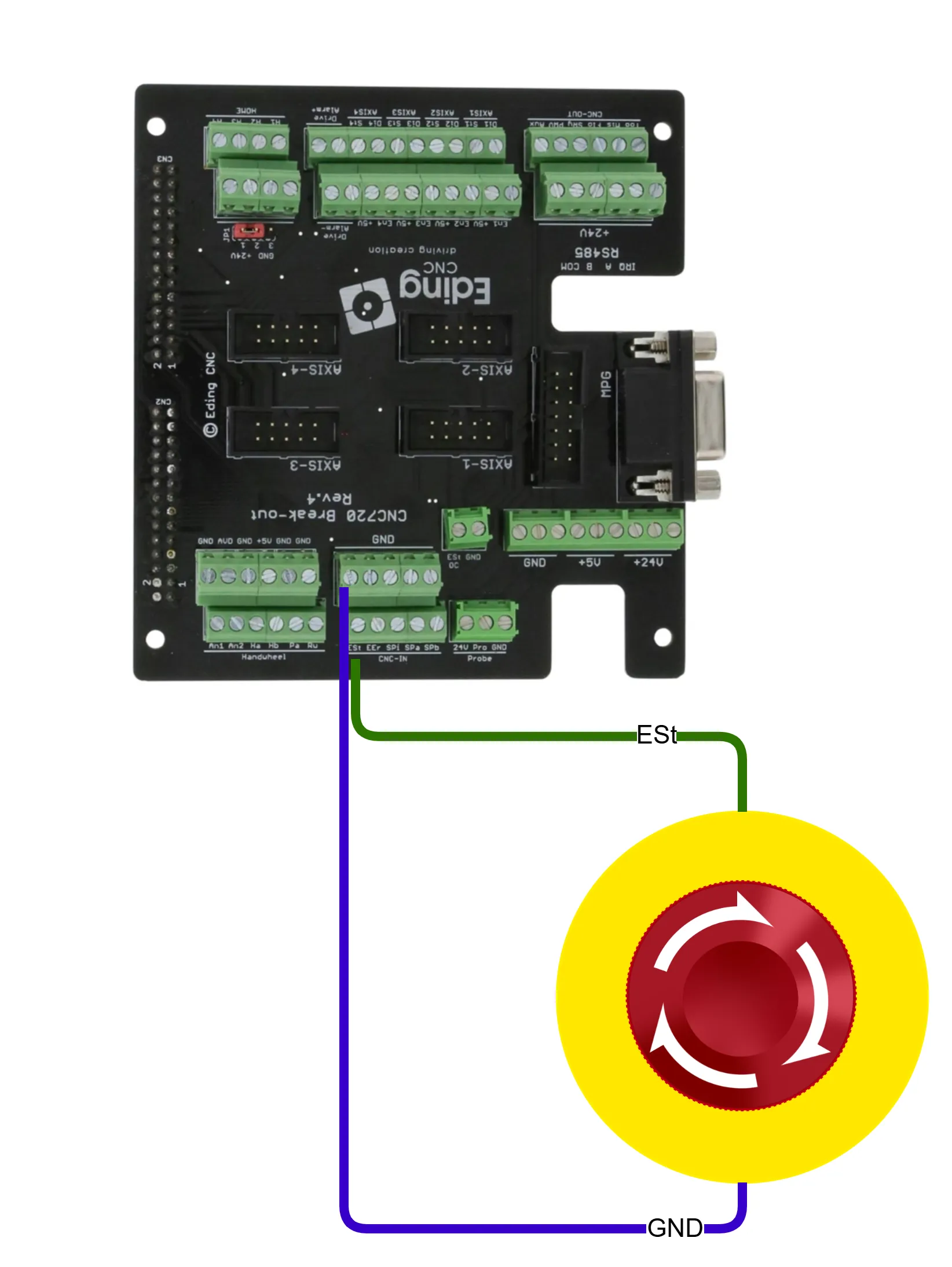
The second option is to connect an E-Stop to the E-Stop input, called 'ESt', on the breakout board.
Using multiple E-Stop elements
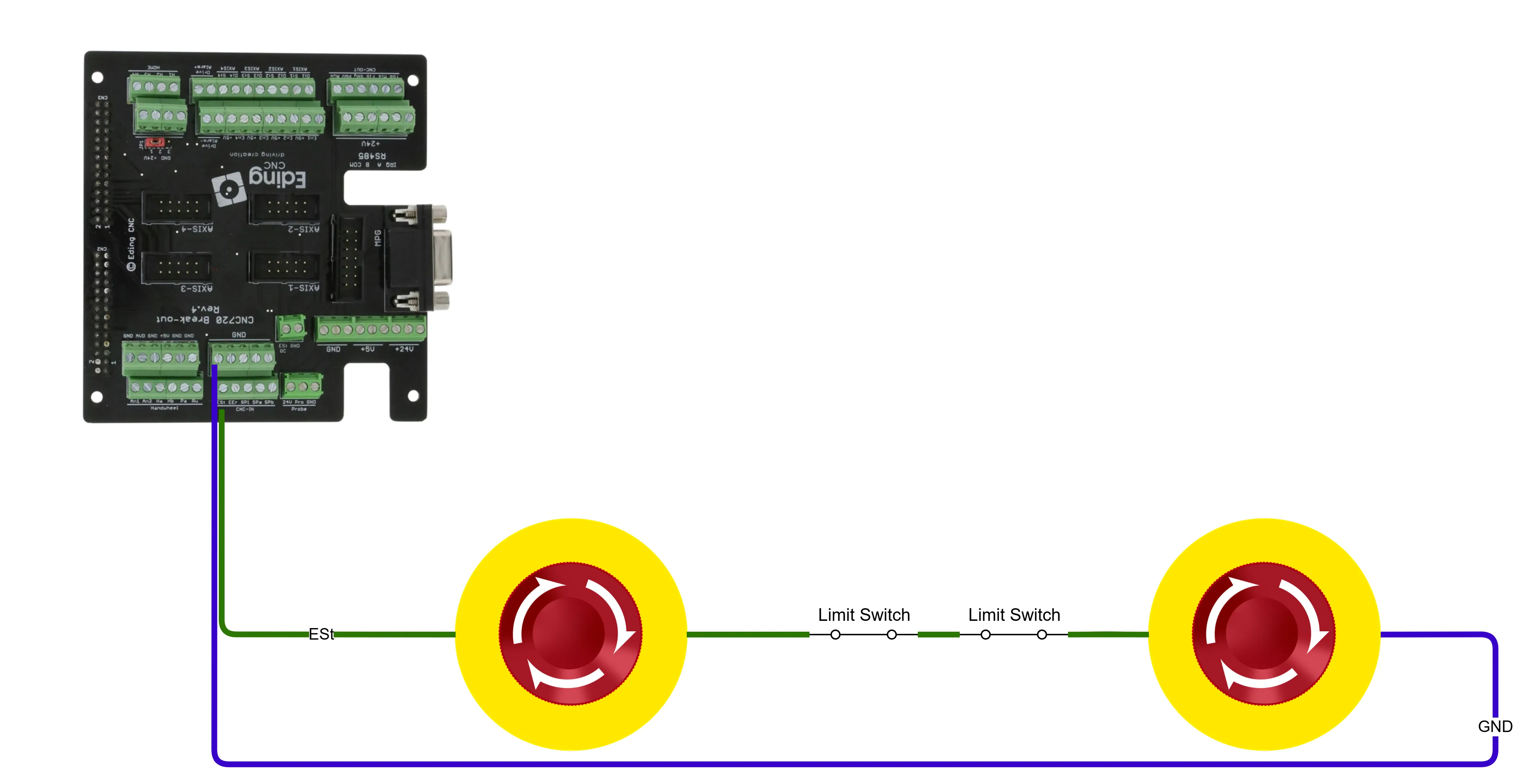
It's also possible to use multiple E-Stop buttons or other elements. For example, if you use limit switches, you could use these together with the E-Stop buttons to cause an e-stop condition.
For more info about the jumpers settings and/or about the E-Stop, take a look at the CNC720 Manual.
Setting up E-STOP in the software
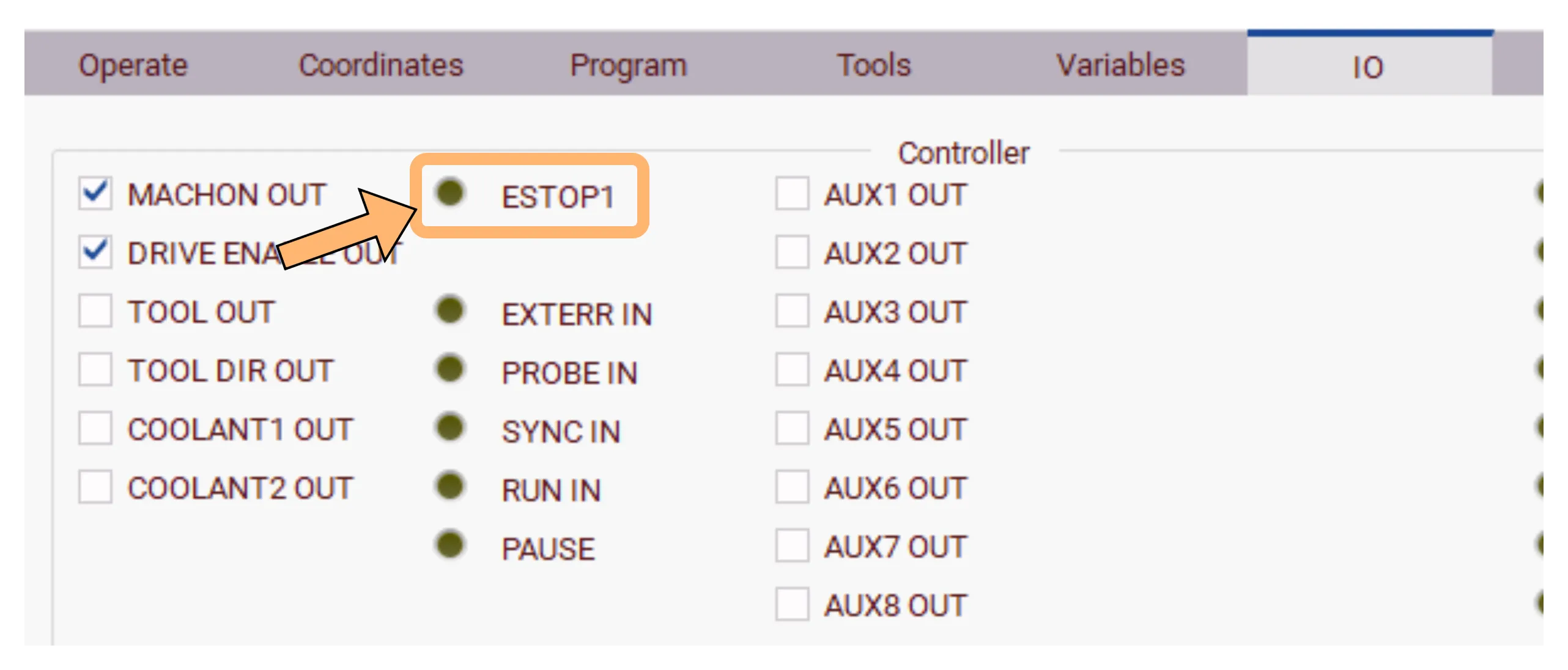
The first step is to check the I/O tab to see whether the E-STOP signal is visible. To do that, go to the 'I/O' tab and verify that the E-STOP input toggles when you activate and deactivate the E-STOP button.
By default, the controller disables outputs through hardware only when an E-stop occurs. To signal the E-stop to the operator, some additional software setup is required.
With the machine connected and powered up, start the software and navigate to Setup> Safety> Emergency Stop.
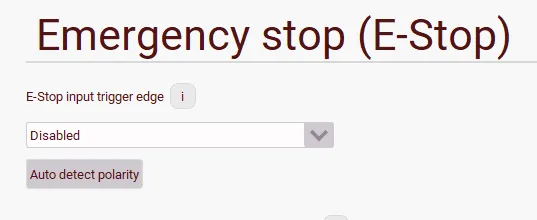
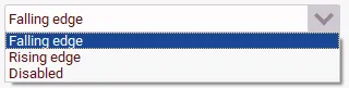
In the E-Stop input trigger edge dropdown, select Falling edge.
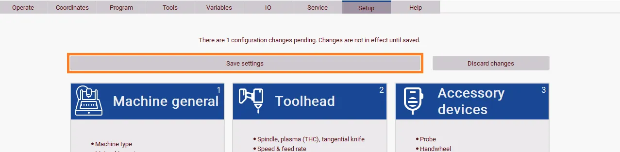
Press 'Back' and 'Save settings'.
Testing
Ensure that all E-stop switches are not activated/pressed. With the software open, press the 'Reset' button. The E-stop indicator should be turned off.
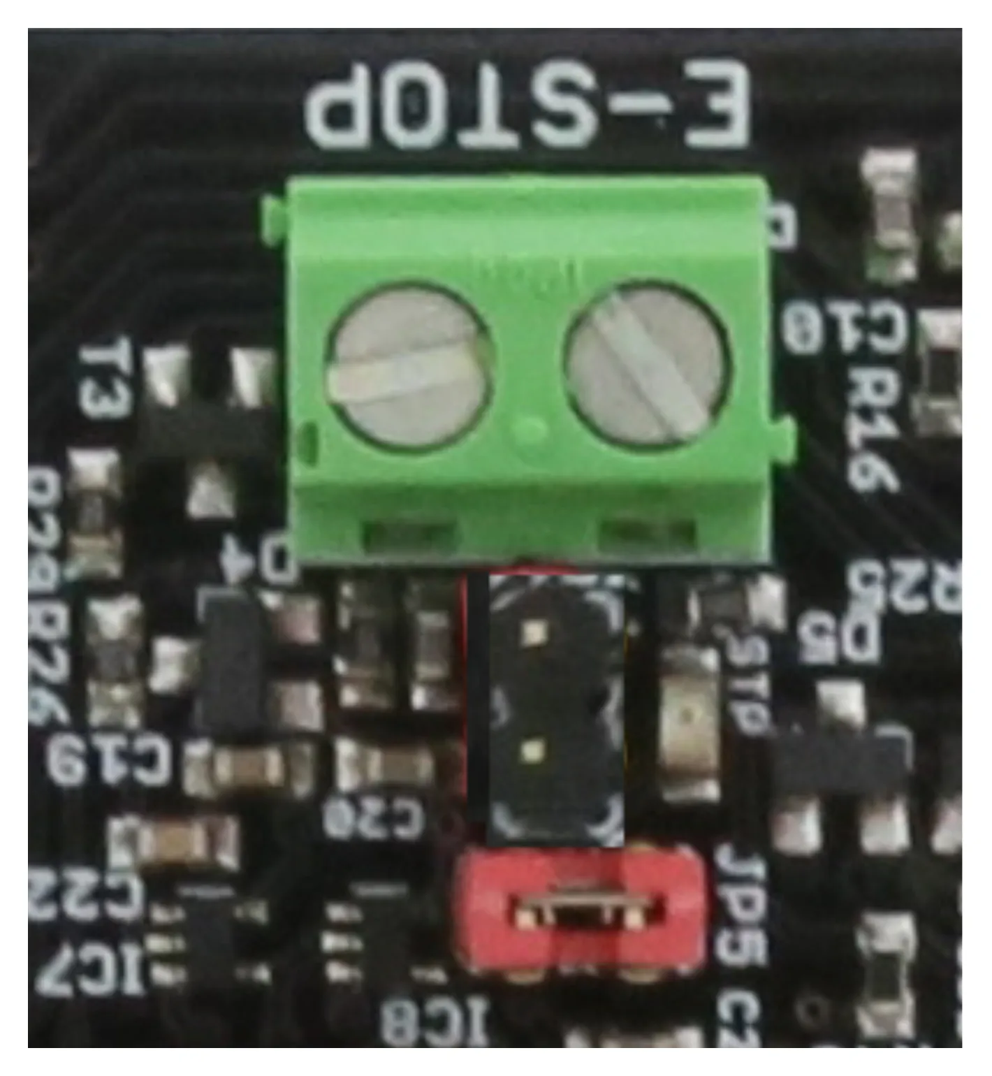
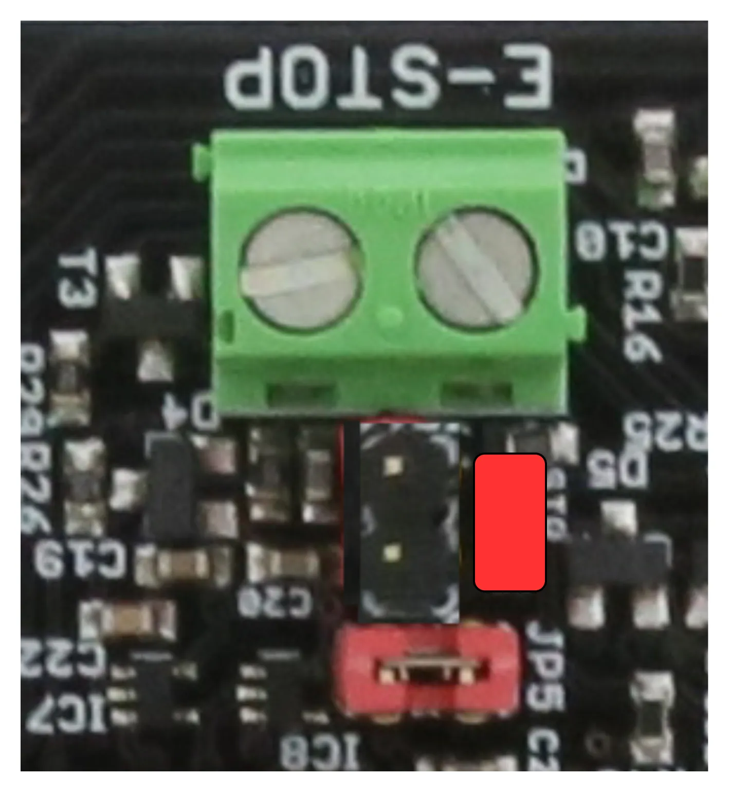
If the indicator does not turn off, check the wiring.
The 'Operate' tab in the software should not show any indications of an E-stop condition.
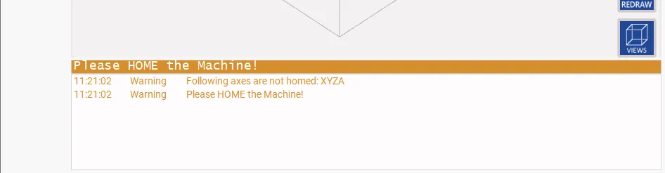
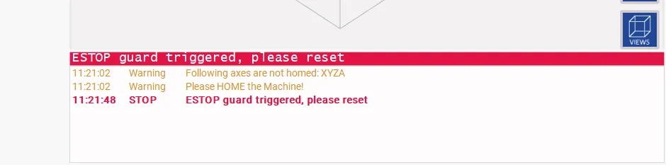
If the software does show an E-stop message, the settings applied in the Configuration section have to be checked.
Press (one of) the E-stop switch(es); the E-stop indicator on the PCB will turn red, and the software will show an E-stop message.
Unlatch the E-stop button and press 'Reset'. The E-stop message will clear when all switches are released.
One last note, a CNC machine can be dangerous. Try to use proper safety measures. These safety measures must be external to the controller. The controller's E-stop feature is NOT a substitute for external safety relays or similar devices.