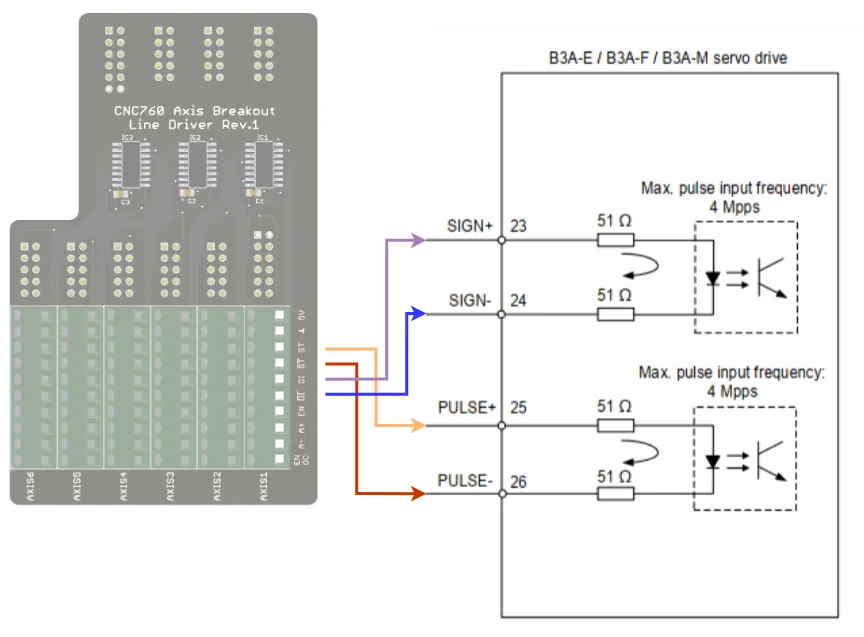
CNC760 connected to Delta ASDA B3 Servo
Make sure you understand our drive. So, first check the drive's manual. Some things may depend on a specific type of Delta drive.
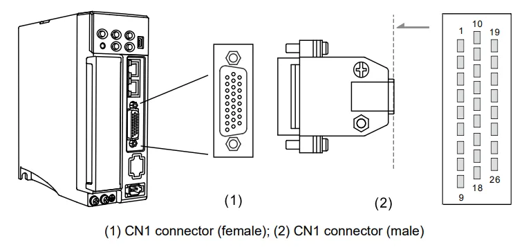
To connect the controller to the Delta drive, we use the so-called 'CN1' connector.
The image belows show where this is found. Again, this can be different depending on your version of the controller.
From the Delta manual, the following connections can be identified for controlling the position:
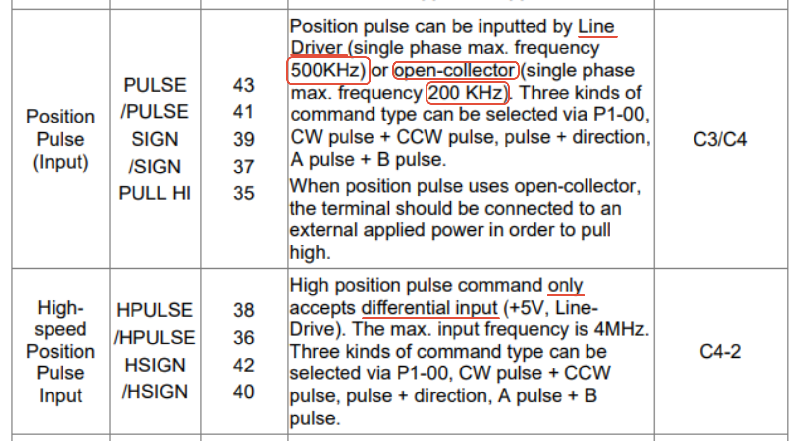
It's important to understand that the Delta has two control inputs, 'Position Pulse' and 'High-speed Position Pulse Input'. The main thing to understand is that the 'High-speed' inputs only use differential inputs.
Which breakout to use?
There are two breakout boards for the controller signal: the 'Axis breakout' or the 'Axis line driver breakout'. The main difference is that the 'axis breakout' will offer single-ended signals, so just one wire with either a high or low signal level at a TTL 5V. The advantage is that it is very simple to use. Most stepper or servo drives can use this system.
The second option, the 'Axis linedriver breakout', will generate differential signals. This means it's a two-wire system, and the signal will appear on both wires but with opposite values. The biggest advantage of these systems is that, at higher frequencies, the signal is less susceptible to interference from external sources.
You need to check the drive's manual to determine the best option.
Maximum step frequency
It's important to understand the maximum step frequency the drive accepts. In this case, it shows that the 'Position' input takes signals of either 500kHz or 200kHz in an open-collector configuration, or up to 4MHz when using differential signals. The CNC760 can generate a step frequency up to 400kHz. Perhaps it's not necessary to use this high frequency.
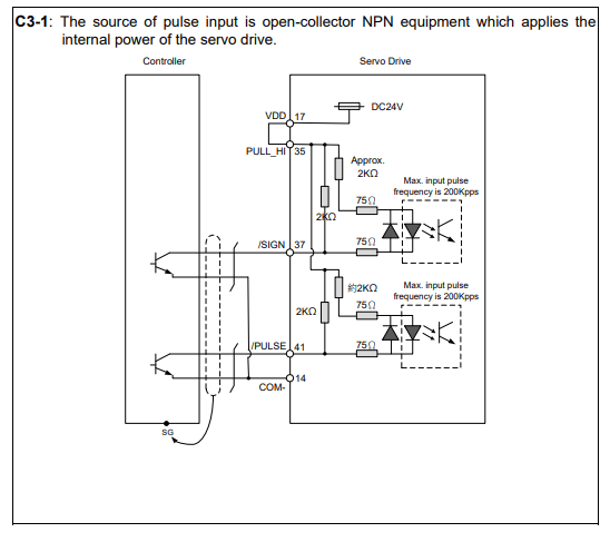
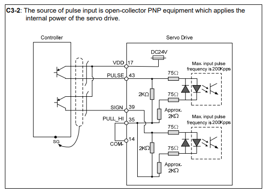
In the images below, the manual shows two configurations for controlling the drive's signals. If you look closely, you see that it talks about an open-collector configuration, and operating at 24V. Since the 'axis breakout' board only generates a TTL 5V signal, this method is not advisable.
The best way to connect to this drive is to use the line driver option.
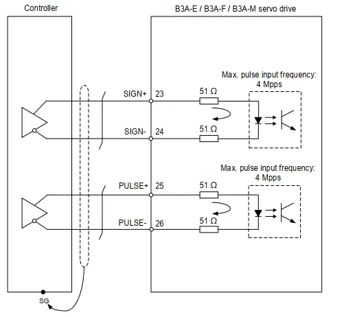
CNC760 Axis line driver connecting
The signals that need to be connected arein the table below:
'!' indicates the inverter signal:
CNC 760 breakout signals | Signal Delta |
|---|---|
Step+ / ST | PULSE+ |
Step- / !ST | PULSE- |
Direction+ / DI | SIGN+ |
Direction- / !DI | SIGN- |